




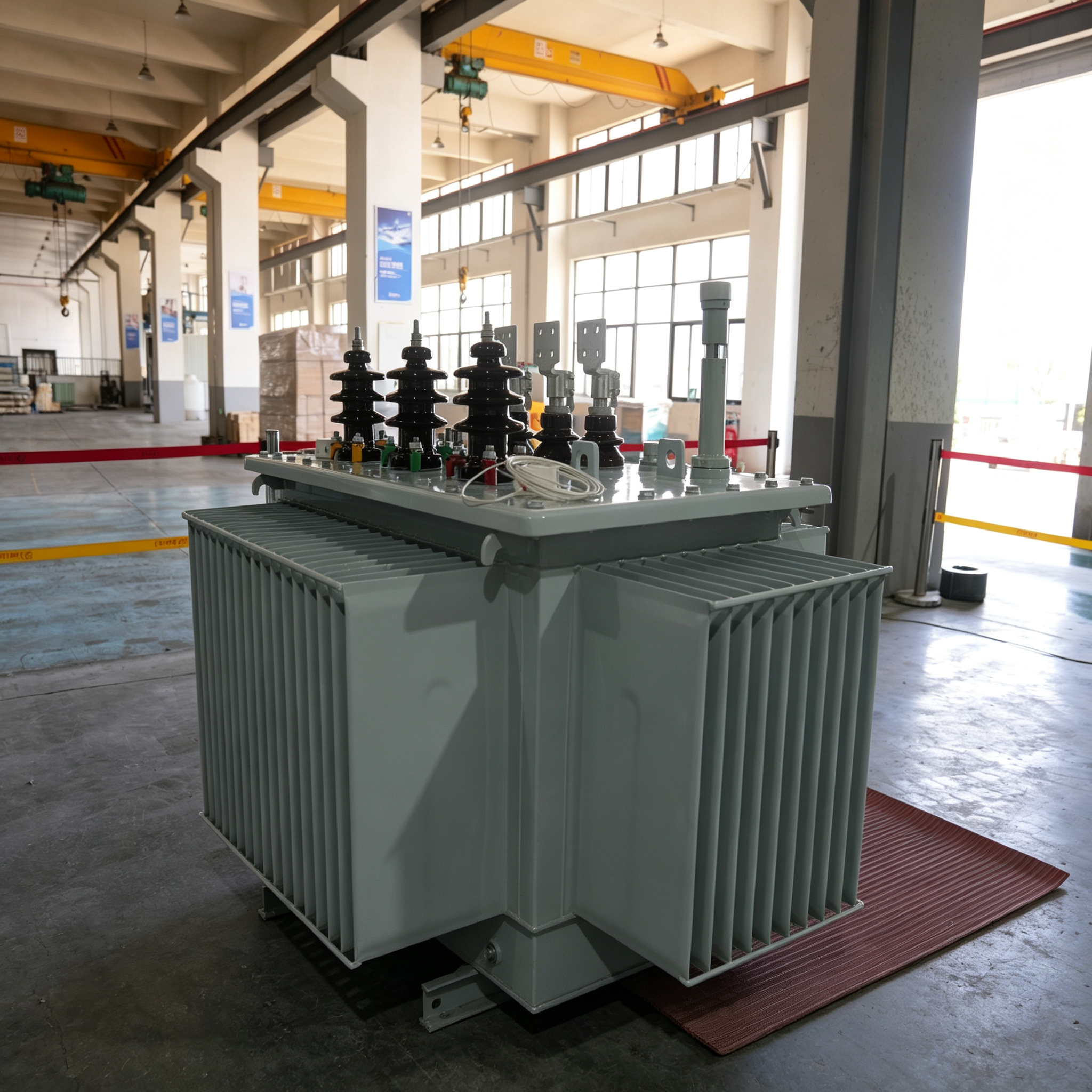
China Oil Immersed Distribution & Power Transformers Factory: Reliable Suppliers for Utility and Industrial Needs
Characteristics
- The transformer core is made of amorphous alloy band, no-load loss is 60% lower than that of S9 transformer and 25% lower than the stipulated value of JB/T10318.
- The transformer adopts Ddyn11 to reduce the effect of harmonic wave to power grid and improve power supply quality.
- The transformer adopts vacuum casting tank core, which greatly improves the reliability and stability.
- The transformer adopts vacuum oiling method, which fully eliminates the bubbles, forming into oil tank.
- According to years of practical experiences, our products adopt advanced technology, so the winding insulation and lightning impulse test's full-wave peak voltage is 25% higher than that of national standard, thus to make sure that the transformer can run safely and reliably.
Core Specifications
- Width of band: 142mm, 170mm, 213mm
- Height of core aperture: 150-1000mm
- Width of core aperture: 65-500mm
- Thickness of folded core aperture: 20-180mm
- Core height: Width of band+4mm (cooling thickness epoxy resin)
- Width of band+2mm (cooling thickness of gunmetallic)
- Thickness of folded core joint: Thickness of folded core x 1.18mm
- Perimeter of outer max band is 3500mm.
Main Parameters
| Rated capacity (kVA) |
Voltage combination and tapping range (kV) | Vector group | No-load loss (W) |
Load loss (W) |
No-load current (%) |
Impedance voltage (%) |
|---|---|---|---|---|---|---|
| 30 | High voltage 6, 6.3, 10, 10.5, 11 High voltage tapping range ±5±2×2.5 Low voltage 0.4 |
Dyn11 | 33 | 600 | 1.70 | 4.0 |
| 50 | 43 | 870 | 1.30 | |||
| 63 | 50 | 1040 | 1.20 | |||
| 80 | 60 | 1250 | 1.10 | |||
| 100 | 75 | 1500 | 1.00 | |||
| 125 | 85 | 1800 | 0.90 | |||
| 160 | 100 | 2200 | 0.70 | |||
| 200 | 120 | 2600 | 0.70 | |||
| 250 | 140 | 3050 | 0.70 | |||
| 315 | 170 | 3650 | 0.50 | |||
| 400 | 200 | 4300 | 0.50 | |||
| 500 | 240 | 5160 | 0.50 | |||
| 630 | 320 | 6200 | 0.30 | |||
| 800 | 380 | 7500 | 0.30 | |||
| 1000 | 450 | 10300 | 0.30 | |||
| 1250 | 530 | 12000 | 0.20 | 4.5 | ||
| 1600 | 630 | 14500 | 0.20 | |||
| 2000 | 750 | 17400 | 0.20 | |||
| 2500 | 900 | 20200 | 0.20 | 5 |
Type SH16-M Technical Parameters
| Type | Rated capacity (kVA) |
Voltage combination (kV) | Vector group | No-load loss (W) |
Load loss (W) |
No-load current (%) |
Impedance voltage (%) |
Outline dimensions (mm) L H B |
Installation center distance (L1xL2) (mm) |
Weight of oil (kg) |
Total weight (kg) |
|---|---|---|---|---|---|---|---|---|---|---|---|
| SH16-M-50/10 | 50 | High voltage 6, 6.3, 10, 10.5, 11 High voltage tapping range ±5±2×2.5 Low voltage 0.4 |
Dyn11 | 38 | 870 | 0.9 | 4.0 | 950 1040 620 | 400x650xΦ14 | 160 | 680 |
| SH16-M-100/10 | 100 | 58 | 1500 | 0.7 | 4.0 | 1060 1070 770 | 400x650xΦ14 | 190 | 890 | ||
| SH16-M-160/10 | 160 | 78 | 2200 | 0.5 | 4.0 | 1050 1150 930 | 400x650xΦ14 | 230 | 1190 | ||
| SH16-M-200/10 | 200 | 90 | 2600 | 0.5 | 4.0 | 1110 1170 930 | 550x650xΦ19 | 270 | 1300 | ||
| SH16-M-250/10 | 250 | 110 | 3050 | 0.5 | 4.0 | 1180 1180 1010 | 550x650xΦ19 | 300 | 1460 | ||
| SH16-M-315/10 | 315 | 130 | 3650 | 0.4 | 4.0 | 1180 1180 1010 | 550x650xΦ19 | 240 | 1400 | ||
| SH16-M-400/10 | 400 | 160 | 4300 | 0.4 | 4.0 | 1200 1180 1010 | 550x650xΦ19 | 280 | 1660 | ||
| SH16-M-500/10 | 500 | 190 | 5150 | 0.4 | 4.0 | 1270 1300 1160 | 660x700xΦ19 | 300 | 1950 | ||
| SH16-M-630/10 | 630 | 230 | 6200 | 0.3 | 4.5 | 1450 1330 1240 | 820x700xΦ19 | 480 | 2450 | ||
| SH16-M-800/10 | 800 | 280 | 7500 | 0.3 | 4.5 | 1520 1460 1380 | 820x700xΦ19 | 520 | 2900 | ||
| SH16-M-1000/10 | 1000 | 330 | 10300 | 0.3 | 4.5 | 1720 1510 1460 | 820x700xΦ19 | 680 | 3500 | ||
| SH16-M-1250/10 | 1250 | 390 | 12000 | 0.2 | 4.5 | 1760 1650 1330 | 820x700xΦ19 | 800 | 3980 | ||
| SH16-M-1600/10 | 1600 | 470 | 14500 | 0.2 | 4.5 | 1980 1710 1380 | 820x700xΦ19 | 850 | 5350 | ||
| SH16-M-2000/10 | 2000 | 570 | 17400 | 0.2 | 5.0 | 2085 1790 1545 | 820x700xΦ19 | 1010 | 6350 | ||
| SH16-M-2500/10 | 2500 | 680 | 20200 | 0.2 | 5.0 | 2400 2350 1500 | 820x700xΦ19 | 1050 | 8200 |
Voltage Class & Power Frequency Withstand Voltage
| Voltage class (kV) |
Highest voltage for equipment Effective value of Maximum phase voltage (kV) |
Rated short-time power frequency withstand voltage Effective value of Power-frequency withstand voltage (kV/min) |
Rated lightning impulse withstand voltage Full wave peak value of rated voltage Lightning impulse withstand voltage (kV) |
|---|---|---|---|
| 0.6 | ≤1.1 | 3 | — |
| 3 | 3.5 | 18 | 40 |
| 6 | 6.9 | 25 | 60 |
| 10 | 11.5 | 35 | 75 |
| 20 | 23 | 50 | 125 |
Frequently Asked Questions (FAQ)
What are the primary benefits of using an amorphous alloy core transformer?
Amorphous alloy core transformers significantly reduce energy waste. They offer a no-load loss that is 60% lower than traditional S9 transformers and 25% lower than the standard requirements of JB/T10318, leading to high operational efficiency and cost savings.
How does the Ddyn11 vector group improve power quality?
The Ddyn11 connection configuration helps mitigate the negative effects of harmonic waves on the power grid. This design choice effectively improves the overall power supply quality and enhances grid stability.
What safety testing standards do these transformers meet?
These transformers utilize advanced winding insulation technologies, allowing them to withstand lightning impulse tests with full-wave peak voltages that are 25% higher than the national standard, ensuring safe and reliable operation.
Why is vacuum casting and oiling used during manufacturing?
Vacuum casting of the tank core improves structural stability. Additionally, the vacuum oiling method completely eliminates air bubbles inside the oil tank, which prevents partial discharge and enhances insulation reliability.
What voltage classes are supported by these transformers?
The technical parameters cover voltage classes ranging from 0.6 kV up to 20 kV, with rated lightning impulse withstand voltages reaching up to 125 kV for the 20 kV class equipment.