




GCS Low Voltage Withdrawable Switchgear - Reliable Energy Distribution Solutions from China Suppliers & Factory
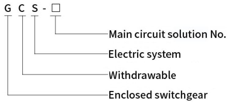
Model meaning
Conditions of use
Product characteristics
Strong commonality of structure and flexible assembly: The switchgear is a fully assembled combination structure, with installation holes of 20mm and 100mm modules on the side, with diameter of φ 9.2mm, making internal installation flexible and convenient.
Independent Compartments: The compartments of the switchgear can be divided into functional unit room, busbar room and cable room. The functions of each functional unit are relatively independent, and the areas are strictly separated by continuously grounded metal plate or pressed flame-retardant plastic plate to ensure safe use and prevent the spread of accident.
Robust Surface Treatment & Grounding: All structural components inside the switchgear shall be galvanized and passivated. The door panels and side panels around the switchgear are made of high-quality cold-rolled steel plates processed and formed by CNC machine tool, and then the surface is treated with acid washing, phosphating, and electrostatic spraying for wear and corrosion resistance. It has both strong mechanical strength and reliable grounding protection continuity.
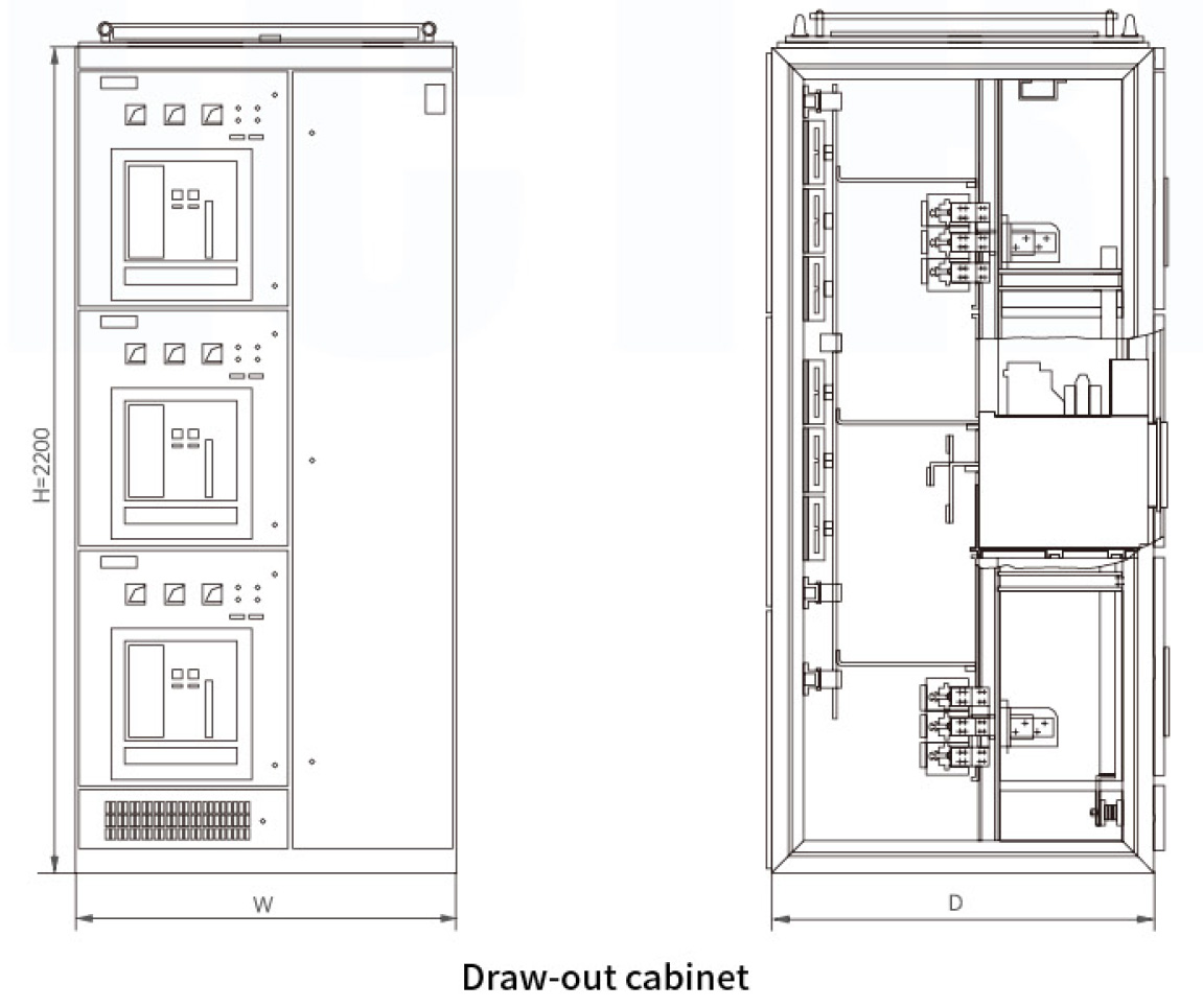
Advanced Draw-out Unit Interlock: The draw-out unit of the switchgear has connection position, test position, disconnection position, draw-out position and isolation position. Each draw-out unit and switch is equipped with mechanical interlock device: the draw-out unit can only be pulled out and inserted when the switch is in the open state, and cannot be pulled out or inserted when the switch is in the closed state. To prevent unauthorized operation, the operating mechanism handle can be locked in the open position with a padlock. Functional draw-out units of the same specification can be easily interchanged, with each draw-out unit corresponding to a maximum of 36 pairs of auxiliary contacts, which can meet the needs of remote operation control, electricity metering and computer interface automation monitoring system.
Optimized Busbar & Cable Layout: The horizontal main busbar is flatly arranged at the back of cabinet to enhance the busbar's ability to resist electric power, which is a basic measure to make the main circuit of the device have high short-circuit strength. The vertical busbar is assembled in insulated functional board to prevent phase discharge caused by switch arcing on the vertical busbar, improving the product's electric shock protection ability and safe operation rate. The design of the cable compartment makes it very convenient for cables to enter and exit both up and down.
Technical parameter
| Parameter Name | Value / Specification |
|---|---|
| Rated insulation voltage (V) | AC660 |
| Rated working voltage(V) | AC380V(AC400) |
| Rated current of horizontal busbar(A) | ≤4000A |
| Rated current of vertical busbar(A) | 1000A |
| Maximum current of draw-out circuit(A) | 400A |
| Rated frequency(Hz) | 50(60) |
| Peak withstand current of horizontal busbar(kA) | 105, 176 |
| Short time withstand current of horizontal busbar(kA/1S) | 50, 80 |
| Peak withstand current of vertical busbar(kA) | 105 |
| Short time withstand current of vertical busbar(kA/1S) | 50 |
| Rated power frequency withstand voltage(V/1min) | 2500 |
| Secondary power frequency withstand voltage(V/1min) | 2500 |
| Enclosure protection level | IP40 |
| Enclosure dimension(mm) | Width 600(800,1000) × Depth 800(1000) × Height 2200 |
| Effective height of functional unit(mm) | 1760 |
Switchgear and draw-out types
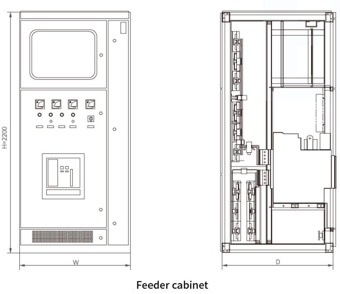
According to the purpose, it can be classified into: incoming cabinet, bus-tie cabinet, feeder cabinet (motor centralized control cabinet, lighting distribution cabinet), and reactive power compensation cabinet. According to the incoming method, it can be classified into four types: upper incoming and upper outgoing, upper incoming and lower outgoing, lower incoming and upper outgoing, and lower incoming and lower outgoing.
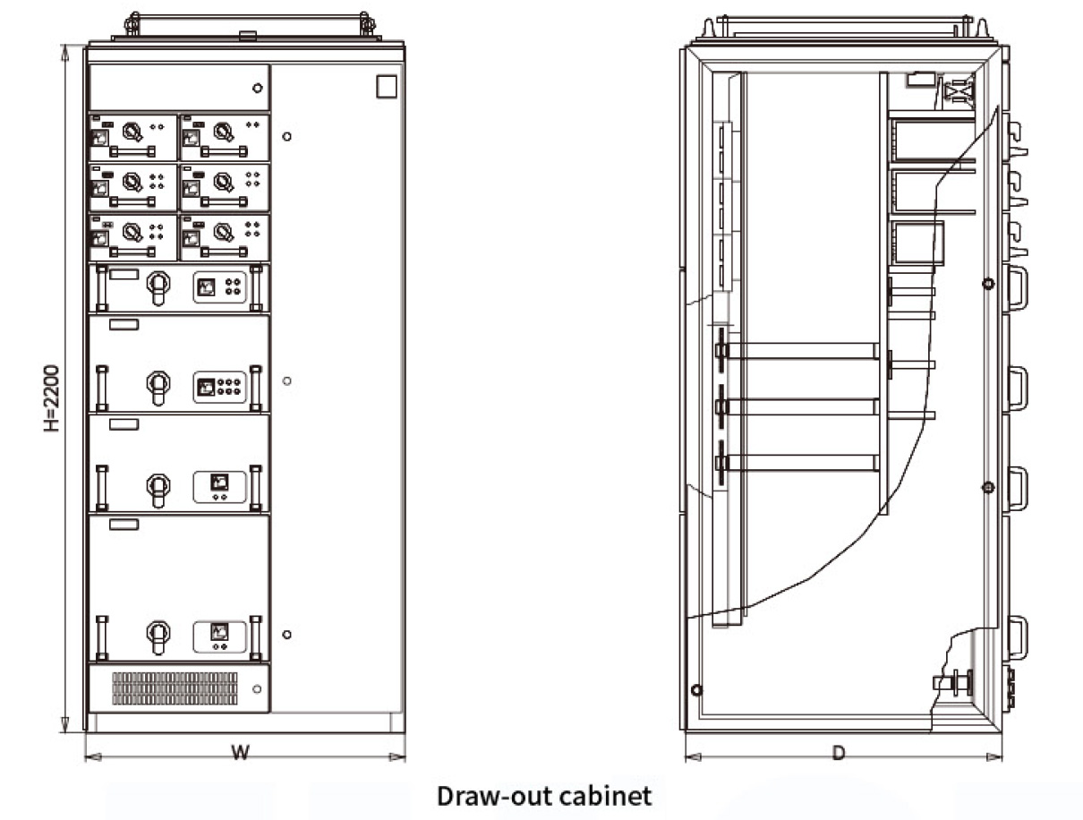
There are five specifications for draw-out unit height, all based on a unit height of 160mm: 1/2 unit, 1 unit, 3/2 unit, 2 unit and 3 unit in five sizes. Draw-out circuit current is 400A or below.
Outline and installation dimension of switchgear
| Name of switchgear | Width (W) | Depth (D) | Height (H) | Cable outlet (FXG) |
|---|---|---|---|---|
| Incoming cabinet | 600、800、1000 | 800、1000 | 2200 | |
| Bus-tie cabinet | 800、1000 | |||
| Feeder cabinet | 800、1000 | 200×400、400×400 | ||
| Draw-out cabinet | 800、1000 | 200×350、400×350 | ||
| Compensation cabinet | 800、1000 |
Note: The above are recommended sizes. Users with special size requirement can negotiate with our company
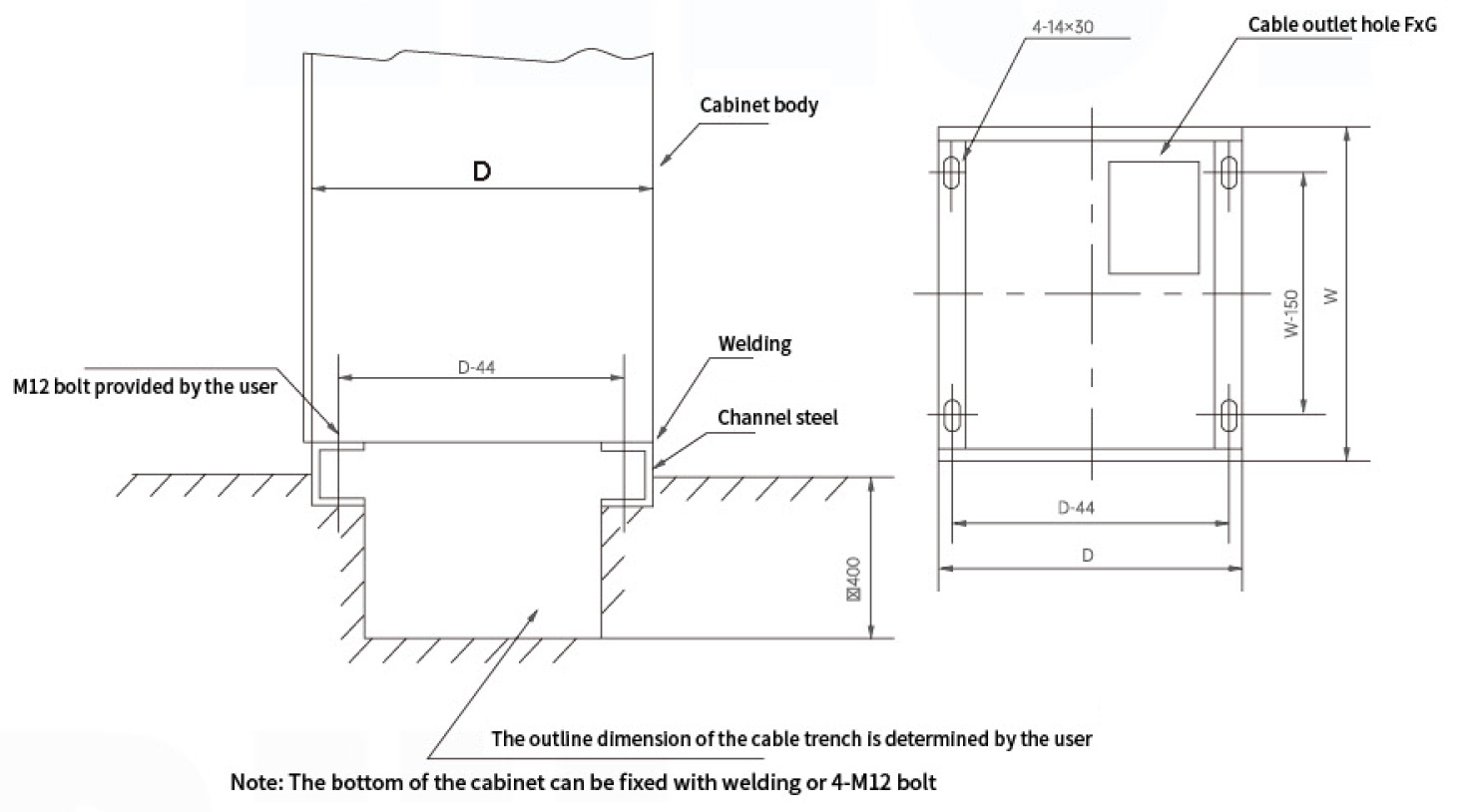
Mounting dimension
Installation diagram
Frequently Asked Questions
1. What are the normal ambient air temperature limits for this switchgear?
The upper limit of the ambient air temperature is +40℃, and the lower limit is -5℃. The average temperature within 24 hours should not exceed +35℃. Under storage and transportation conditions, the minimum allowable temperature is -30℃.
2. What is the maximum installation altitude for standard usage?
The standard rated installation altitude for this switchgear is ≤2000m. For usage conditions exceeding this altitude, please consult the manufacturer for customization options.
3. What is the enclosure protection level (IP rating) of the switchgear?
The standard enclosure protection level for this switchgear is IP40, providing reliable protection against solid foreign objects greater than 1mm.
4. Can functional draw-out units of the same specification be interchanged?
Yes, functional draw-out units of the exact same specification are designed to be easily interchanged for convenient maintenance and configuration changes.
5. What safety interlock mechanisms are integrated into the draw-out units?
Each draw-out unit is equipped with a mechanical interlock device: the unit can only be inserted or pulled out when the switch is in the open (OFF) state. It cannot be moved when the switch is closed. Additionally, the operating handle can be locked in the open position with a padlock to prevent unauthorized operation.
6. What are the standard height specifications for the draw-out units?
There are five height specifications based on a basic unit height of 160mm: 1/2 unit, 1 unit, 3/2 unit, 2 unit, and 3 unit. These specifications support draw-out circuit currents of 400A or below.