

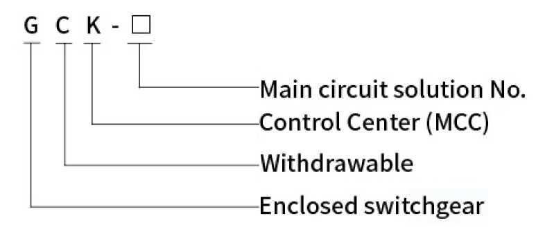
GCK Low Voltage Withdrawable Switchgear - China Suppliers & Factory for Reliable Power Distribution Solutions
Upper limit: +40℃, lower limit: -5℃. 24h average ≤ +35℃. Storage/transportation limit: -30℃.
Max 50% at +40℃ in clean air. Higher humidity allowed at lower temperatures (e.g., 90% at +20℃). Consider occasional condensation.
Vertical inclination ≤ 5°. Install in areas free from severe vibration, impact, or corrosive media.
Strong commonality of structure and flexible assembly: The switchgear is a fully assembled combination structure, with the basic framework assembled by FA steel. The outline dimension and opening dimension of the cabinet framework and components vary according to the basic modulus E=25mm.
Compartment Isolation: The compartments of the switchgear can be divided into functional unit room, busbar room and cable room. The functions of each functional unit are relatively independent, and the areas are strictly separated by continuously grounded metal plate to ensure safe use and prevent the spread of accident.
Durable Construction: All structural components inside the switchgear shall be galvanized and passivated. The door panels and side panels around the switchgear are made of high-quality cold-rolled steel plates processed and formed by CNC machine tool, and then the surface is treated with acid washing, phosphating, and electrostatic spraying for wear and corrosion resistance. It has both strong mechanical strength and reliable grounding protection continuity.
Advanced Interlocks & Interchangeability: The draw-out unit of the switchgear has connection position, test position and disconnection position. Each draw-out unit and switch is equipped with mechanical interlock device: the draw-out unit can only be pulled out and inserted when the switch is in the open state, and cannot be pulled out or inserted when the switch is in the closed state. To prevent unauthorized operation, the operating mechanism handle can be locked in the open position with a padlock. Functional draw-out units of the same specification can be easily interchanged, with each draw-out unit corresponding to a maximum of 20 pairs of auxiliary contacts, which can meet the needs of remote operation control, electricity metering and computer interface automation monitoring system.
| Rated insulation voltage | AC690V |
| Rated working voltage | AC380V(AC400V) |
| Rated current of horizontal busbar | 1250A, 1600A, 2000A, 3200A, 4000A |
| Rated current of vertical busbar | 1000A |
| Maximum current of feeding circuit | 2500A |
| Maximum current of draw-out circuit | 630A |
| Maximum capacity of control motor | 320kW |
| Rated frequency | 50Hz |
| Peak withstand current of horizontal busbar | 105kA, 176kA |
| Short time withstand current of horizontal busbar (1s) | 50kA, 80kA |
| Peak withstand current of vertical busbar | 63kA, 105kA |
| Short time withstand current of vertical busbar (1s) | 30kA, 50kA |
| Rated power frequency withstand voltage (1min) | 2500V |
| Secondary power frequency withstand voltage (1min) | 2500V |
| Enclosure protection level | IP40 |
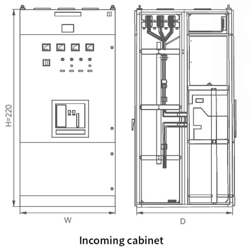
| Enclosure dimension (mm) | Width 600(800, 1000) × Depth 800(1000) × Height 2200 |
| Effective height of functional unit (mm) | 1800 |
| Name of switchgear | Width (W) | Depth (D) | Height (H) |
|---|---|---|---|
| Incoming cabinet | 600, 800, 1000 | 800, 1000 | 2200 |
| Bus-tie cabinet | 600, 800, 1000 | ||
| Feeder cabinet | 600, 800, 1000 | ||
| Draw-out cabinet | 600, 800 | ||
| Compensation cabinet | 600, 800, 1000 |
Note: The above are recommended sizes. Users with special size requirements can negotiate with our company.
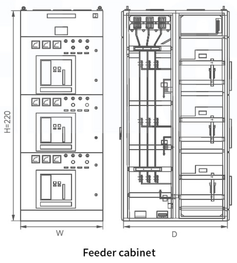
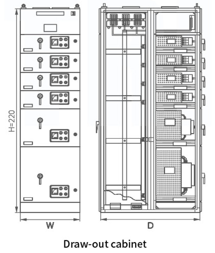
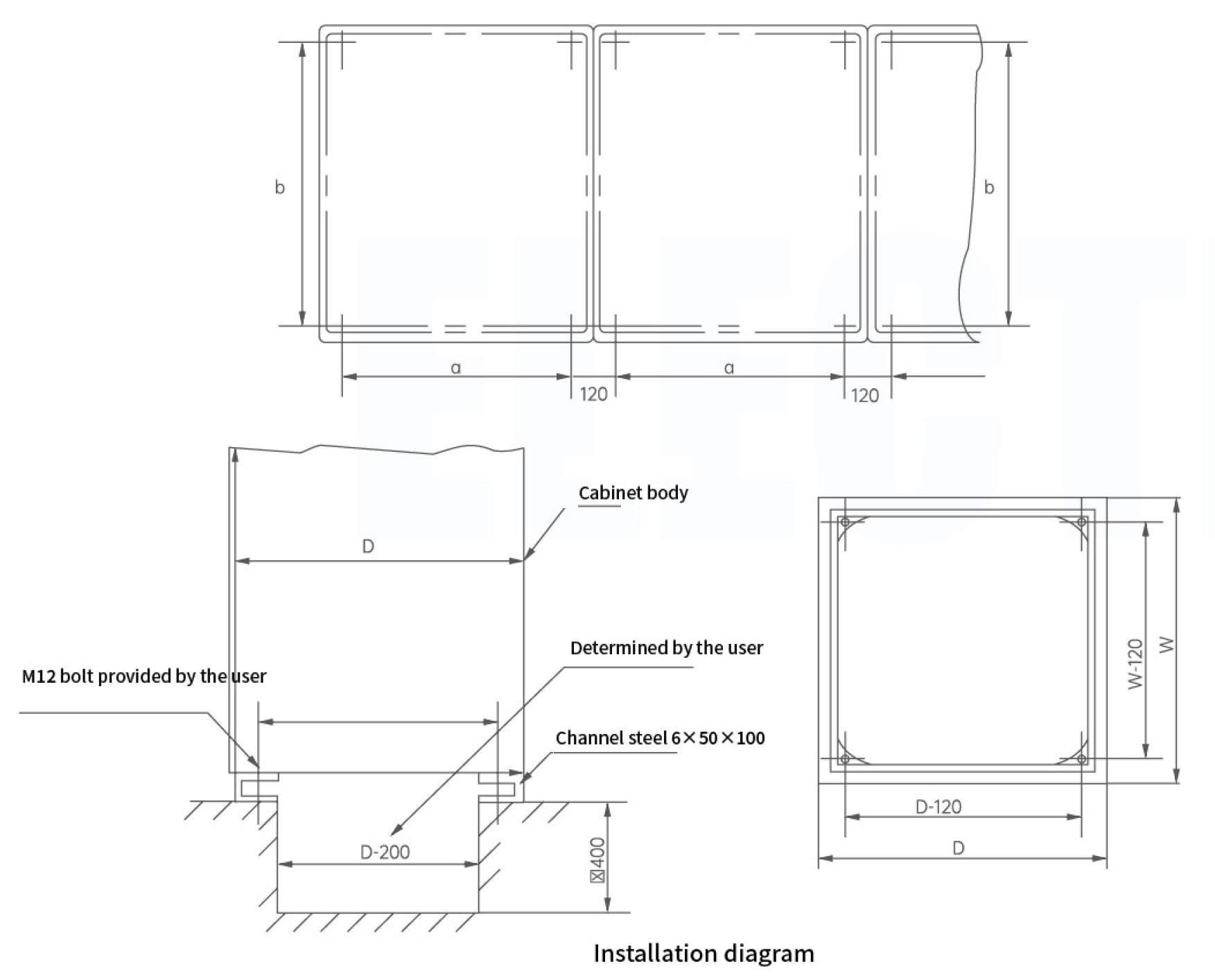
| Outline dimension (mm) | a | b | |
|---|---|---|---|
| Width | 600 | 480 | |
| 800 | 680 | ||
| Depth | 1000 | 880 | |
| 800 | 680 | ||
| 1000 | 880 |