


Hot Products


0102030405

China Suppliers Low Voltage Withdrawable Switchgear for Power Distribution | Factory Quality Equipment
Conditions of Use
- The ambient air temperature shall not be higher than +40℃ and not lower than -5℃, and its average temperature within 24 hours shall not be higher than +35℃;
- Relative humidity: in clean air, it doesn’t exceed 50% at a maximum temperature of +40°C; higher relative humidity is allowable at lower temperatures (e.g. 90% at +20°C): however, it should be considered that occasional condensation may occur due to temperature change.
- Altitude shall not exceed 2000m;
- This equipment is suitable for transportation and storage at temperatures ranging from -25℃ to +55℃, and it can reach +70℃ in a short period of time (not exceeding 24 hours). At these extreme temperatures, the equipment should not suffer any irreparable damage and should be able to function normally under normal conditions;
Note: When the above normal service conditions cannot meet the usage requirement, it shall be negotiated between the user and the manufacturer.
When this equipment is used on offshore oil drilling platforms and nuclear power plants, a separate technical agreement should be signed.
Technical Parameters
| Rated insulation voltage | AC690V | |
| Rated working voltage | AC400V | |
| Rated current of main busbar | ≤6300A | |
| Rated withstand current of main busbar (1s) | 50kA, 80kA | |
| Rated peak withstand current of main busbar | 105kA, 176kA | |
| Maximum working current of distribution busbar (vertical busbar) | 1000A | |
| Distribution busbar (peak current of vertical busbar) | ||
| Standard type | 105kA(maximum)/0.1s | |
| Enhanced type | 176kA(maximum)/0.1s | |
Protection Level
Compliant with IEC529 and DIN40050 standards:
- IP30 provides protection for solid larger than φ2.5MM
- IP40 provides protection for solid larger than φ1.0MM
- IP54 provides protection against dust and splash in any direction
When ordering IP54 protection level, it should be negotiated with the manufacturer.
Cabinet Structure
The basic structure of the switchgear cabinet is assembled by C-shaped profiles. C-shaped profiles are made by bending steel plates with E=25mm as the modular installation hole.
All cabinet frames and inner partitions are treated with galvanized purification. The surrounding door panels and side panels are coated with high-voltage electrostatic spraying.
The basic structure of the cabinet is shown in Figure 1: the basic dimensions of the cabinet are shown in Figure 2, Tables 1 and 2.
Switch Cabinet Type
- Power distribution center cabinet (PC): Emax, MT, 3WN, AH, ME series circuit breakers can be used.
- Motor control center cabinet (MCC): Assembled from draw-out units of various sizes, the main switch of each circuit adopt high breaking molded case circuit breaker or rotary load switch with fuse, Power factor automatic compensation cabinet (with manual, automatic and remote power factor compensation device).
Technical Drawings & Installation
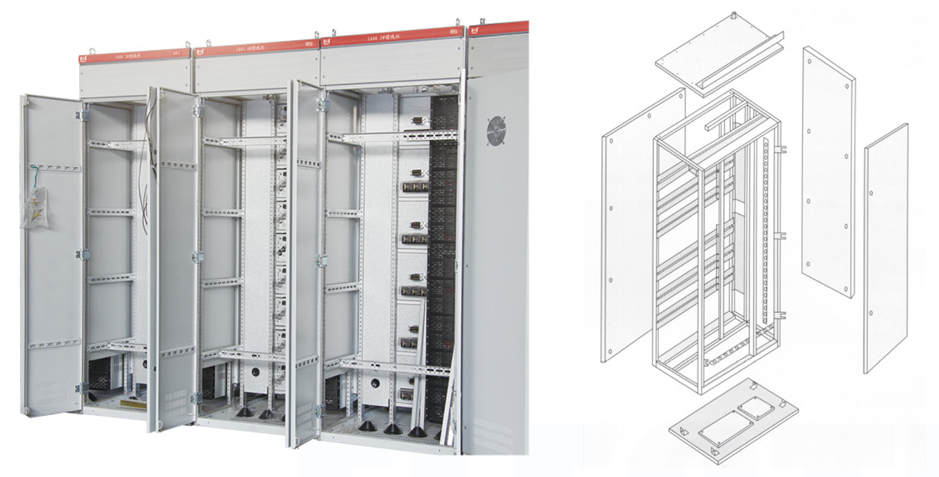
Figure 1: Cabinet frame structure composed of C-shaped profiles
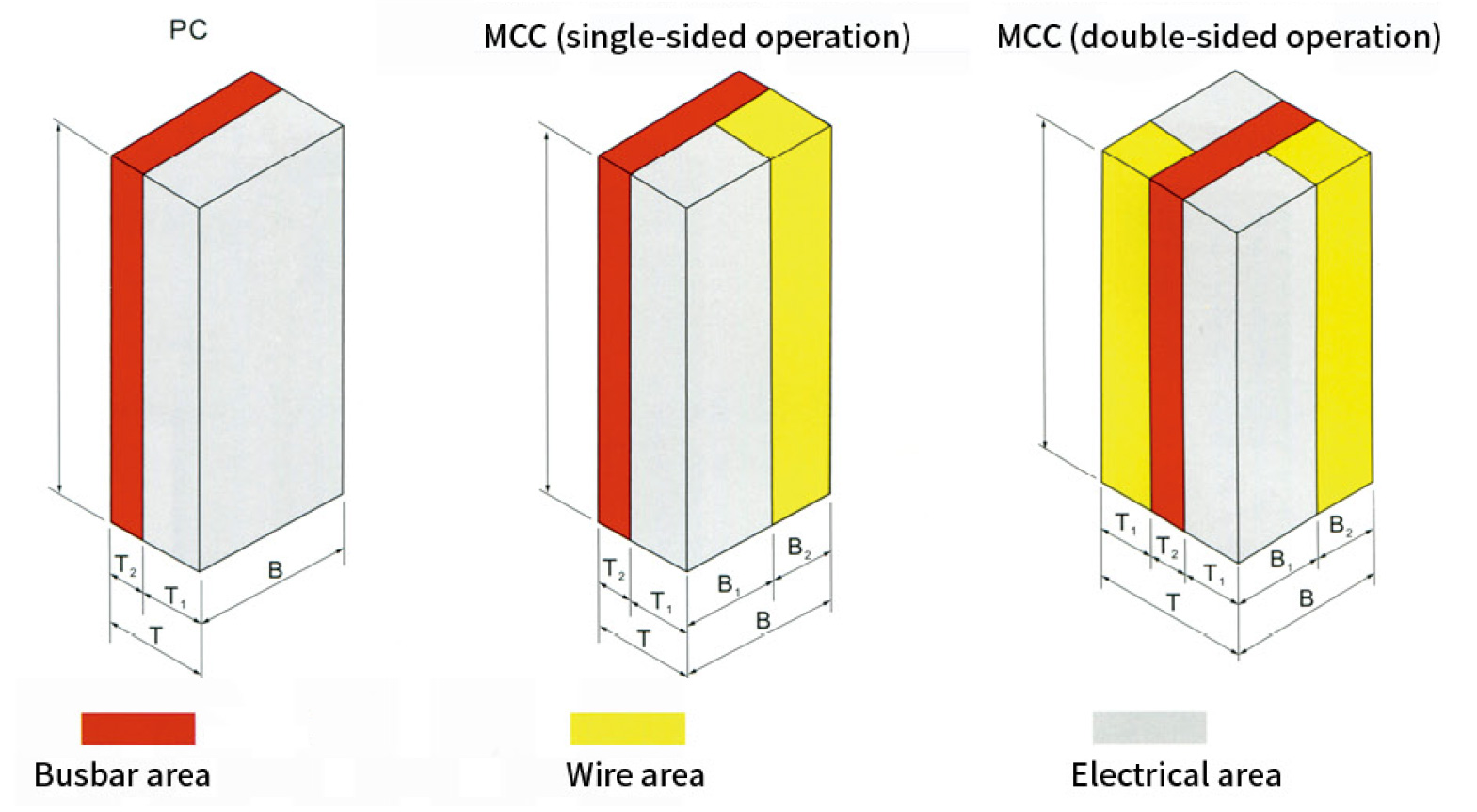
Figure 2: Cabinet schematic diagram
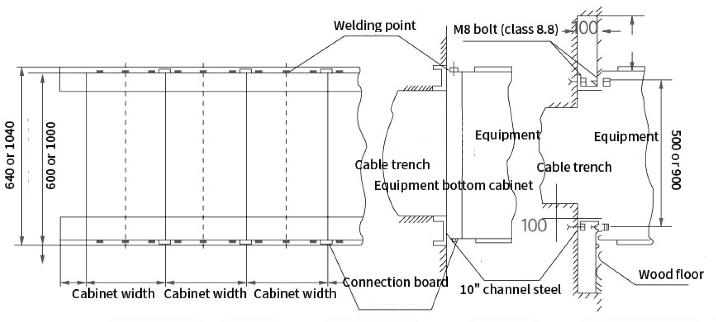
Installation Diagram (Solution 1: Welding / Solution 2: Bolt)
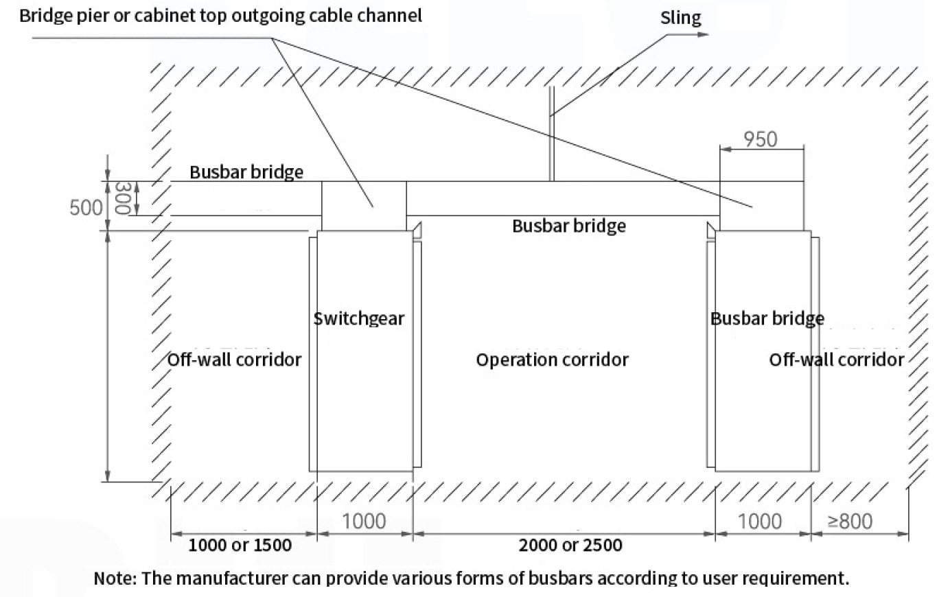
Installation diagram of busbar bridge
Frequently Asked Questions (FAQ)
What are the environmental temperature limits for this switchgear?
The ambient air temperature must be between -5℃ and +40℃. The average temperature over any 24-hour period should not exceed +35℃.
What is the maximum installation altitude for this equipment?
The equipment is designed to operate safely at an altitude not exceeding 2000 meters above sea level.
Can the switch cabinet be used under extreme storage conditions?
Yes, it is suitable for transportation and storage within a temperature range of -25℃ to +55℃. It can withstand up to +70℃ for short periods (not exceeding 24 hours) without suffering irreparable damage.
What protection levels (IP ratings) are supported?
The cabinet complies with IEC529 and DIN40050 standards. It offers IP30 (protection for solids >2.5mm), IP40 (protection for solids >1.0mm), and IP54 (protection against dust and splashes). IP54 must be negotiated with the manufacturer during ordering.
What is the difference between the PC and MCC cabinet types?
The Power Distribution Center (PC) cabinet utilizes major circuit breakers like Emax, MT, 3WN, AH, and ME. The Motor Control Center (MCC) cabinet is assembled from draw-out units of various sizes, using high-breaking molded case circuit breakers or rotary load switches with fuses.
What installation methods are available for this system?
The equipment supports two standard installation solutions: Solution 1 (Welding installation) and Solution 2 (Bolt installation), as outlined in the technical drawings.