Leave Your Message
China Suppliers Factory: ZGS Series Box-type Substation with Pad-Mounted Transformer for Efficient Power Distribution
Hot Products

China Suppliers Factory: ZGS Series Box-type Substation with Pad-Mounted Transformer for Efficient Power Distribution

,

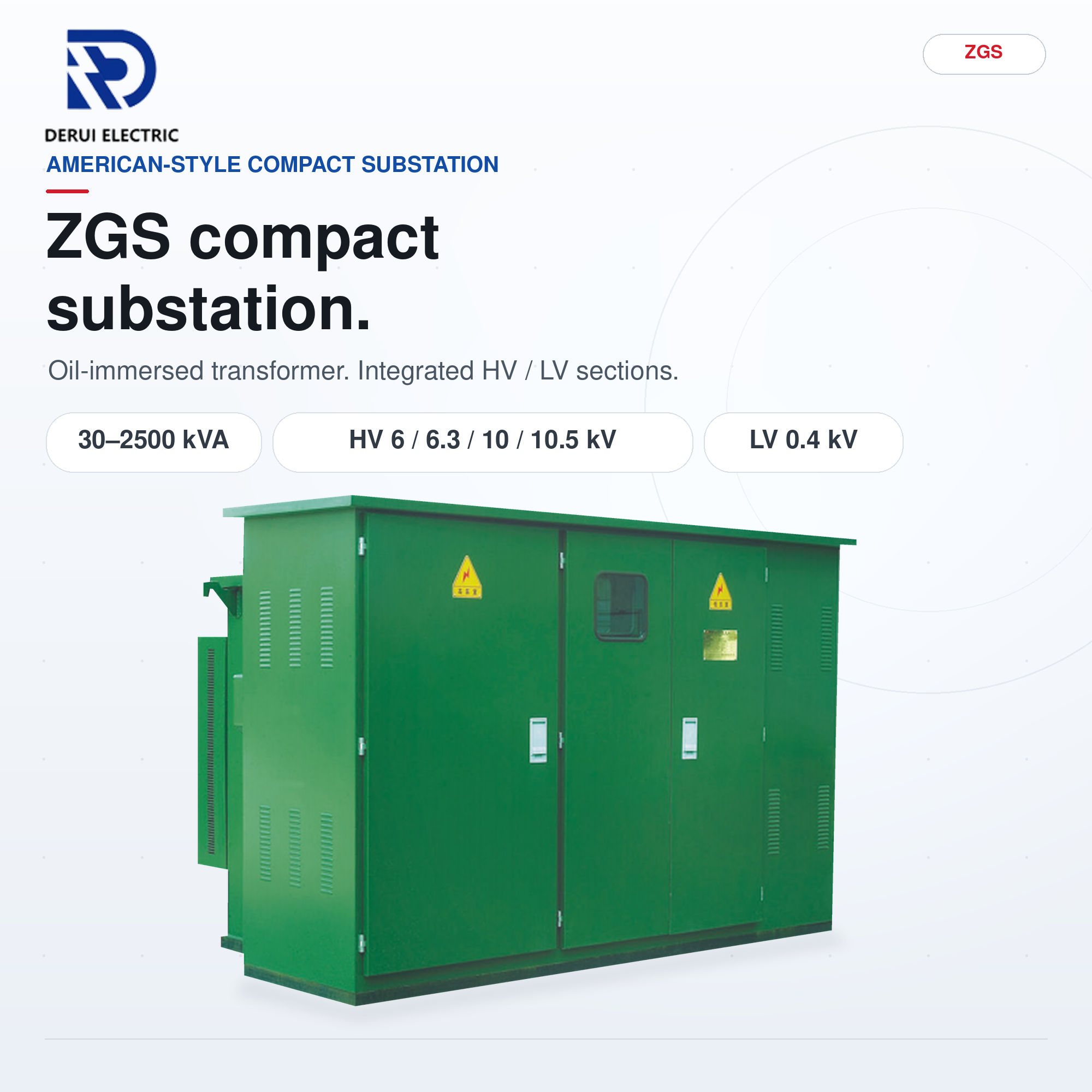
The ZGS □  series combination substation, widely recognized as the American type box substation, features a unique 品-shaped design that facilitates a compact and efficient integration of high and low voltage equipment with the transformer. This innovative structure allows for excellent heat dissipation, as the transformer is exposed to the air on three sides, providing optimal maintenance access by allowing separation from the high and low voltage equipment shell.

,

Our product utilizes a fully enclosed S series oil-immersed transformer equipped with a chip-type oil tank, eliminating the need for an oil conservator. It includes high and low voltage bushings, a tap changer, oil level indication, a pressure relief valve, and an oil relief valve, all strategically positioned on the end plate of the high voltage compartment for easy observation and operation.

,

The separation of high and low voltage compartments with sturdy steel plates ensures that the transformer remains independently functional while still maintaining the integrity of a complete box transformer. This compact, lightweight design is ideal for effective power distribution, with distribution switch equipment conveniently mounted on both the high and low voltage sides. As a leading China manufacturer and supplier, we are committed to delivering high-quality substation solutions tailored to meet your needs.

,

    Model meaning
    Model meaning details
    Conditions of use
    Cooling condition: Air self-cooling;
    Altitude: <1000m;
    Ambient temperature: The outdoor ambient temp shall not exceed 40℃, and not be lower than -45℃. Monthly average temp ≤ 30℃, annual average temp ≤ 20℃;
    Relative humidity: At 25℃, the relative humidity of the air does not exceed 95%, and the monthly average does not exceed 90%;
    Seismic intensity: Horizontal acceleration ≤ 0.3m/s², vertical acceleration ≤ 0.15m/s²;
    Ambient environment: Installation environment should be free of obvious pollution, explosive, corrosive gas and dust;
    Installation site: No severe vibration or impact, and required to be installed on a cement platform or other flat and solid platform;
    Special Note: When the above normal service conditions cannot meet the usage requirements, the user shall negotiate with the manufacturer.
    Product characteristics
    Small size, compact structure, easy installation;
    It can be used for ring network and terminal, and it can reliably protect personal safety;
    Low damage, low noise, superior performance;
    Low temperature rise and high load capacity.
    List of fuse configuration for high voltage protection
    Rated capacity of transformer (kVA) Low voltage side (0.4kV) rated current (A) High voltage side (10kV) rated current (A) Plug-in fuse capacity (A) Backup fuse capacity (A) Low voltage equipped main switch capacity (A)
    50 72.2 2.89 4 or 6 10 100
    80 115.5 4.62 10 20 160
    100 144.3 5.77 10 20 200
    125 180.4 7.22 10 25 250
    160 230.9 9.24 15 40 315
    200 288.7 11.55 20 40 400
    250 360.8 14.43 25 50 500
    315 454.7 48.19 31.5 80 630
    400 577.4 23.09 40 80 800
    500 721.7 28.87 50 100 1000
    630 909.3 36.37 65 125 1250
    800 1154.7 46.19 80 125 1600
    1000 14434 57.75 100 200 2000
    1250 1804.2 72.17 125 250 2500
    1600 2309.4 92.38 160 320 3200
    Main technical parameter table

    Technical parameter of 6kV and 10kV S□ series oil immersed distribution transformer

    Rated capacity kVA Voltage combination KV Connection group symbol Loss kW Off-load current % Short circuit impedance % Weight kg Outline dimension mm L×W×H Track gauge, longitudinal/ transverse
    HV LV Off-load Load 75% Body weight oil weight Total weight
    30 10.5 10 63 0.4 Dyn11 Yzn11 Yyn0 0.08 0.63/0.6 1.5 4 185 70 310 790×660×925 550/400
    50 0.1 0.91/0.87 1.3 255 85 395 820×675×1030 550/400
    63 0.11 1.09/1.04 1.2 280 95 430 845×690×1065 550/400
    80 0.13 1.31/1.25 1.2 320 100 480 865×715×1075 550/550
    100 0.15 1.58/1.5 1.1 380 110 540 880×720×1120 550/550
    125 0.17 1.89/1.8 1.1 444 115 600 910×750×1110 550/550
    160 0.2 2.31/2.2 1 510 130 690 910×750×1200 550/550
    200 0.24 2.73/2.6 1 640 150 840 1220×745×1220 550/550
    250 0.29 3.2/3.05 0.9 720 190 950 1240×775×1345 660/660
    315 0.34 3.83/3.65 0.9 835 200 1065 1230×750×1345 660/660
    400 0.41 4.52/4.3 0.8 1010 240 1255 1330×825×1375 660/660
    500 0.48 5.41/5.15 0.8 1170 260 1485 1455×915×1390 660/660
    630 Dyn11 Yyn0 0.57 6.2 0.6 4.5 1375 320 1800 1540×920×1510 660/660
    800 0.7 7.5 0.6 1620 365 2120 1650×1035×1555 820/820
    1000 0.83 10.3 0.6 1780 405 2450 1855×1235×1600 820/820
    1250 0.97 12 0.5 2065 560 2855 1925×1285×1680 820/820
    1600 1.17 14.5 0.5 2470 650 3400 2025×1355×1730 820/820
    2000 1.55 18.3 0.4 5 2700 695 4460 2190×1900×1950 820/820
    2500 1.83 21.2 0.4 3230 870 5330 2240×1940×1980 1070/1070
    Note 1: The load loss values above the diagonal line in the table are applicable to the Dyn11 or Yzn11 connection group, and the load loss values below the diagonal line are applicable to the Yn0 connection group.
    Note 2: The outline dimensions are for reference only during selection, and the final dimensions are subject to the product's outline drawing.
    Basic structure

    The box substation should be installed on a horizontal concrete platform, which should be able to withstand the weight. Due to the fact that most of the weight of the box substation is concentrated at the rear of the box containing the transformer body, the front cabinet is mostly empty and relatively light in weight. Therefore, the rear of the platform should be sturdy and able to withstand the weight of the combined transformer. Meanwhile, it is also required that the front and rear countertops be flat (generally, it is not easy to achieve flatness, so the foundation of the front cabinet can be slightly lower than that of the rear transformer body, and after being in place, it can be sealed with concrete) to ensure smooth installation of the box substation.

    Basic structure diagram 1
    Basic structure diagram 2
    ① Regarding the combination size of dimensions;
    ② The concrete foundation should have a smooth surface. After the installation of the combined substation, the surrounding area of the base should be sealed with cement;
    ③ The shape of ground bars and cable fixing brackets can be determined according to the actual situation;
    ④ Cable fixing brackets and ground bars should be pre-embedded;
    ⑤ The position of the cable holes for incoming and outgoing lines depends on the specific situation;
    ⑥ After the installation of the combination substation, there must be a gap of no less than 1.5m on the front of the switch to facilitate operation;
    ⑦ The grounding grid can be made of 12 plated round steel or 30 x 4 galvanized flat steel, and the ground wire resistance should meet the requirements of the power department.
    Note: The dimensions of L, W and H are determined according to the actual engineering configuration.
    Frequently Asked Questions (FAQ)
    Q What are the ambient temperature requirements for this distribution transformer?
    The outdoor ambient temperature must not exceed 40℃ and must not be lower than -45℃. Additionally, the monthly average temperature should remain under 30℃, and the annual average temperature should not exceed 20℃.
    Q Can this substation be used in ring network applications?
    Yes, it is designed to be highly versatile and can be used for both ring networks and terminal operations while reliably protecting personal safety.
    Q What type of cooling system does the transformer use?
    The equipment operates under normal cooling conditions utilizing an air self-cooling system.
    Q What are the core installation site requirements for the box substation?
    It must be installed on a smooth, flat concrete platform or solid structure with no severe vibration or impact. Since most weight is concentrated at the rear where the transformer body sits, the rear foundation must be especially sturdy.
    Q What materials are recommended for the grounding grid setup?
    The grounding grid can be constructed using either 12 plated round steel or 30 x 4 galvanized flat steel, ensuring the ground wire resistance meets the standards of your local power department.
    Q What is the required clearance space in front of the switch panel?
    After installing the combined substation, there must be a minimum clearance gap of 1.5 meters on the front side of the switch to facilitate safe and easy operations.