


Hot Products


0102030405

China DR-XGN-24 KV Ring Main Unit - Reliable Metal Closed Switchgear Suppliers & Factory
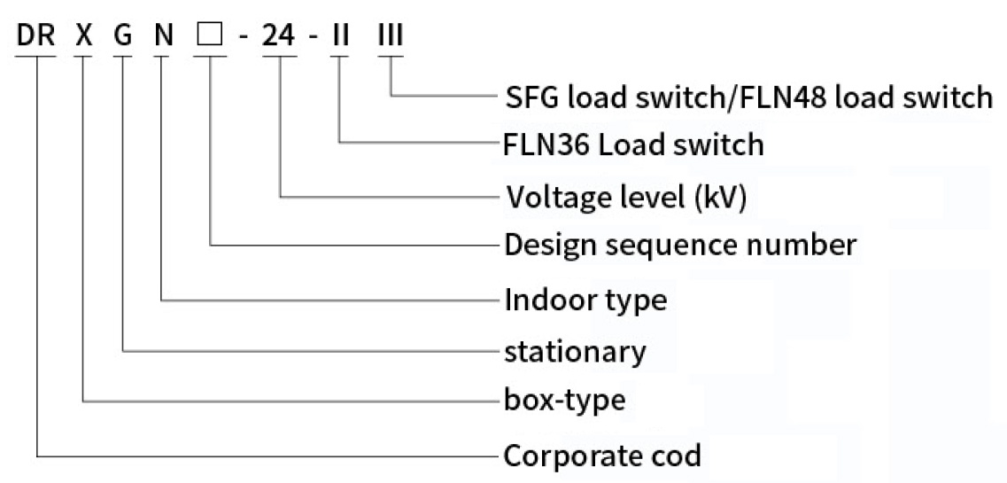
Model meaning
Normal service condition
- Altitude≤1000m
- Maximum ambient temperature+40℃
- Minimum ambient temperature-35℃
- Maximum daily temperature difference25K
- Daily average relative humidity≤95%
- Monthly average relative humidity≤90%
- Earthquake resistancelevel 8
- System rated frequency50Hz
- SF6 leakage rate≤0.1%
- Enclosure protection classIP3X
Main feature
- Increase the main transformer capacity and improve the power supply capacity of the substation.
- Improve the power transmission capacity of distribution lines and reduce the number of distribution lines.
- Increase the power supply radius of the medium voltage line.
This voltage level earlier in a small area trial operation, by the requirements of the State grid company, by Jiangsu provincial pilot promotion of 20kV voltage level, now the southern network is also ready to start promoting 20kV voltage level in Guangdong and other places, it can be predicted that the final 24kV equipment will dominate the market.
Main technical parameters
| Item | Unit | 20kV SF₆ Ring switchgear | ||
|---|---|---|---|---|
| Rated voltage | kV | 24 | ||
| Rated frequency | Hz | 50 | ||
| Rated current | A | 630A≤100 (Load switch-fuse combination cabinet) | ||
| Rated short-circuit breaking current | kA | 31.5 | ||
| Rated closing current (peak) | kA | 50 | ||
| Rated heat stable current | kA/3S | 20 | ||
| Rated dynamic stable current (peak) | kA | 50 | ||
| Insulation level | Power frequency withstand voltage | Phase to phase and ground to ground | kV/1min | 65 |
| Fracture | kV/1min | 79 | ||
| Lightning impulse withstand voltage | Phase to phase and ground to ground | kV | 125 | |
| Fracture | kV | 145 | ||
| Rated active load breaking current | A | 630 | ||
| Rated cable charging breaking current | A | 25 | ||
| Main loop resistance | μΩ | ≤300 | ||
| Kinetic function | Spring type: DC/AC 220V/48V | |||
| Rated transfer current | A | 1400 | ||
| Mechanical life | Load switch: 3000; Ground switch: 2000 | |||
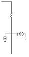
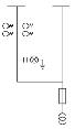
Primary scheme
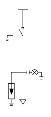
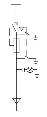
| Primary plan number | DC01 | Primary plan number | DC08 |
| Main bus TMY-3 (40×8) |
|
Main bus TMY-3 (40×8) |
|
| DR-XGN□-24 Primary system diagram | DR-XGN□-24 Primary system diagram | ||
| Disposition | Incoming cabinet | Disposition | Outlet cabinet |
| Load switch FLN□-24D | 1 | Load switch FLN□-24D | |
| Load switch FLRN□-24D | Load switch FLRN□-24D | 1 | |
| Live display DXN-T/Q | 1 | Live display DXN-T/Q | 1 |
| The current transformer | The current transformer | ||
| Fuse XRNP-24/□A | Fuse XRNP-24/□A | ||
| Voltage transformer JDZ-24 | Voltage transformer JDZ-24 | 3 | |
| Lightning arrester HY5WS-33/85 | 3 | Lightning arrester HY5WS-33/85 | |
| Fuse XRNT-24/□A | Fuse XRNT-24/□A | 3 | |
| Measuring instrument | Measuring instrument | ||
| Protection mode | Protection mode | ||
| Auxiliary function | Auxiliary function | ||
| Mode of operation | Manual operation | Mode of operation | Manual operation |
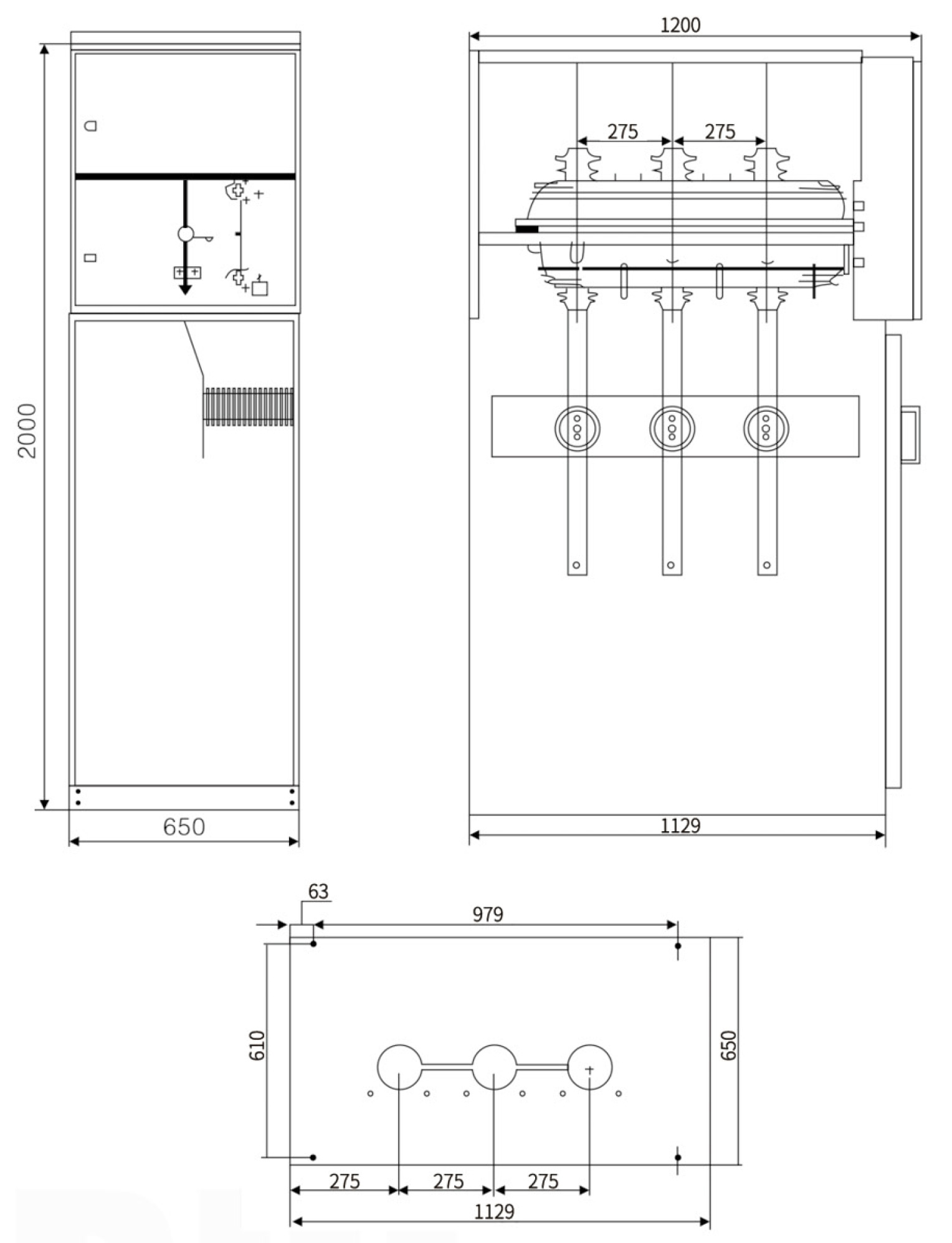
| Cabinet width x Depth x height (mm) | 650×1200×2000 | Cabinet width x Depth x height (mm) | 650×1200×2000 |
| Primary plan number | DC01 | Primary plan number | DC08 |
| Main bus TMY-3 (40×8) |
|
Main bus TMY-3 (40×8) |
|
| DR-XGN□-24 Primary system diagram | DR-XGN□-24 Primary system diagram | ||
| Disposition | Incoming cabinet | Disposition | Outlet cabinet |
| Load switch FLN□-24D | 1 | Load switch FLN□-24D | |
| Load switch FLRN□-24D | Load switch FLRN□-24D | 1 | |
| Live display DXN-T/Q | 1 | Live display DXN-T/Q | 1 |
| The current transformer | The current transformer | ||
| Fuse XRNP-24/□A | Fuse XRNP-24/□A | ||
| Voltage transformer JDZ-24 | Voltage transformer JDZ-24 | 3 | |
| Lightning arrester HY5WS-33/85 | 3 | Lightning arrester HY5WS-33/85 | |
| Fuse XRNT-24/□A | Fuse XRNT-24/□A | 3 | |
| Measuring instrument | Measuring instrument | ||
| Protection mode | Protection mode | ||
| Auxiliary function | Auxiliary function | ||
| Mode of operation | Manual operation | Mode of operation | Manual operation |
| Cabinet width x Depth x height (mm) | 650×1200×2000 | Cabinet width x Depth x height (mm) | 650×1200×2000 |
Overall dimension
Frequently Asked Questions
What are the normal environmental conditions for operating this 20kV/24kV switchgear?
The standard service conditions include an altitude of ≤1000m, ambient temperature limits between -35℃ and +40℃, a maximum daily temperature variance of 25K, and daily average relative humidity of ≤95% (monthly ≤90%).
What is the SF6 leakage rate and enclosure protection class?
The switchgear features a highly reliable sealing system with an annual SF6 leakage rate of ≤0.1%, and it meets the IP3X enclosure protection class standards to prevent external interference.
What are the primary insulation level ratings of this equipment?
The switchgear is rated for a power frequency withstand voltage of 65kV (phase to phase/ground) and 79kV (fracture). The lightning impulse withstand voltage is 125kV (phase to phase/ground) and 145kV (fracture).
How does this switchgear improve power supply efficiency?
It is designed to increase the main transformer capacity, enhance the power transmission capacity of distribution lines (reducing the overall line quantity), and expand the power supply radius of medium voltage lines.
Why is the 24kV voltage level equipment expected to dominate the market?
Following pilot promotions of the 20kV/24kV voltage levels by the State Grid in Jiangsu and upcoming rollouts in Guangdong and other southern regions, market demand is shifting rapidly towards high-efficiency 24kV equipment standards.