


Hot Products


0102030405

High-Voltage Current-Limiting Fuses for Transformer Protection - China Suppliers & Factory for 3.6KV to 40.5KV Solutions
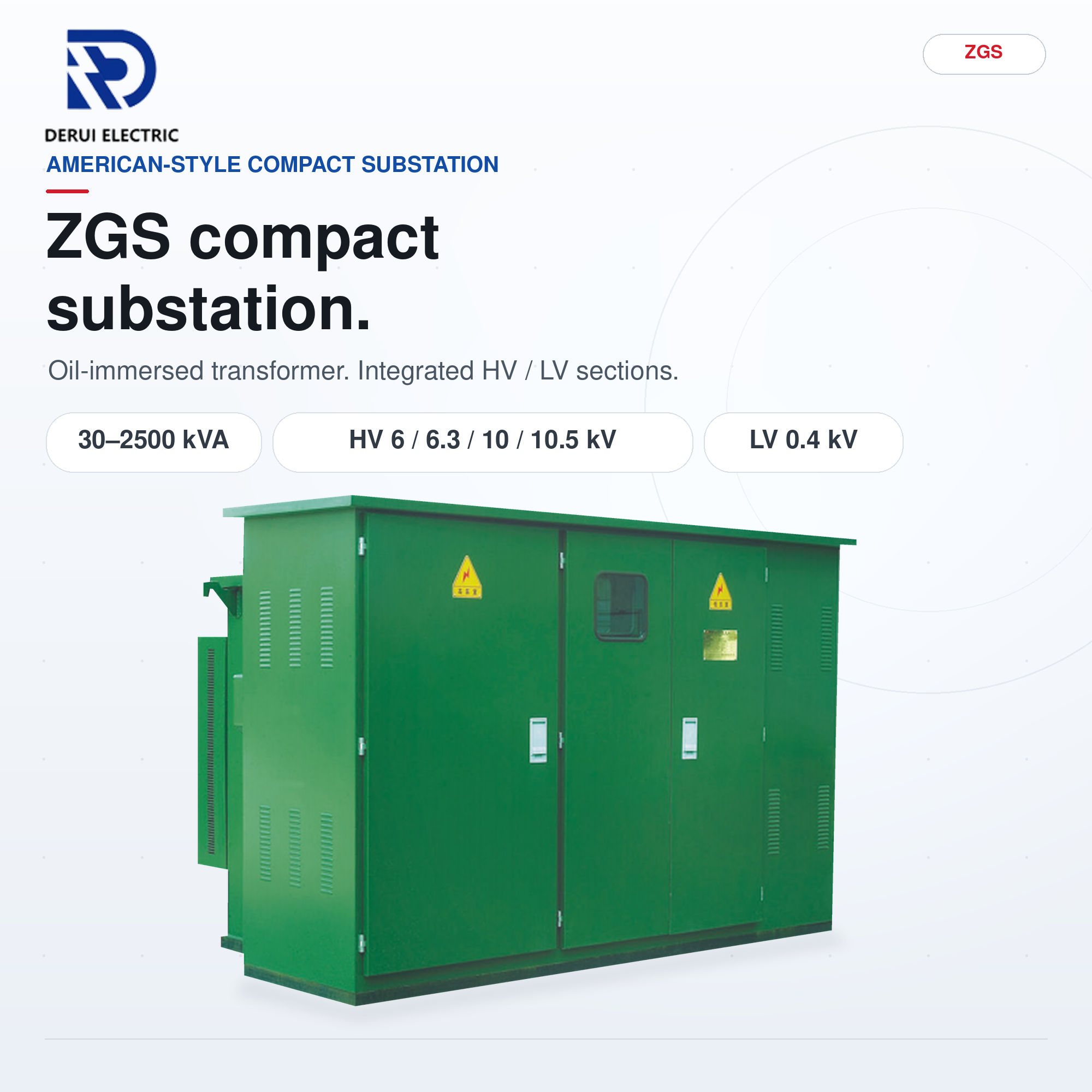
It can be used in indoor systems of 50HZ and rated voltage of 3.6KV, 7.2KV, 12KV, 24KV, 40.5KV; Used together with other switch facilities such as loading switches, vacuum contactors, it can protect electric transformers and other electric facilities against overloading or circuit break. It is also a necessary accessory for high-voltage switchboxes, circular circuit cabinets, and high / low voltage top-loading transformer substations.


Fuse Structure Components
1
End cap
2
Porcelain Tube
3
Arc extinguishing filler
4
Fuse element
5
Coil resistance
6
Impactor
7
Star-shaped skeleton
Technical Data
| Type | Rated Voltage (KV) | Rated Current (A) | Dimension (MM) |
|---|---|---|---|
| XRNT-12 | 12 | 3.15-200A | 51*292 / 76*292 / 88*292 |
| XRNT-24 | 24 | 3.15-200A | 51*442 / 76*442 / 88*442 |
| XRNT-36 (40.5) | 36 (40.5) | 3.15-200A | 51*537 / 76*537 / 88*537 |
| Dimension: Can be customized | Color: Brown / White | Material: Ceramic / Epoxy | |
Considerations for Transformer Fuses
To ensure proper transformer protection, in addition to considering the transformer's full-load current, allowable overload current, and surge current, the following selection principles should also be considered:
1
The fuse's time-current curve should lie to the right of the transformer's surge current.
2
The fuse's rated current should meet the transformer's full-load current.
3
If the fuse is installed in an enclosed cabinet or the ambient temperature exceeds standard requirements, consider derating.
4
The secondary-side high-voltage fuse and the secondary-side low-voltage protective device should be properly coordinated. The current corresponding to the intersection of the high-voltage fuse's time-current characteristic (minimum pre-arcing) and the low-voltage protective device's characteristic (maximum total operating characteristic appropriately converted to the high-voltage side) should be greater than the maximum high-voltage short-circuit current caused by a secondary-side short circuit.
5
The pre- and post-breaking currents of a fuse without a striker should be less than the maximum breaking current of the switchgear with which it is used.
6
When the transformer secondary side is grounded and short-circuited, the transformer primary side phase current distribution ratio will be 1:2:1. At this time, the maximum current on the primary side will be 3/2 times the normal conversion factor. This situation must be taken into consideration when selecting a short-term solution.
Frequently Asked Questions (FAQ)
What are the primary applications of these high-voltage fuses?
These fuses are designed for indoor systems of 50HZ with rated voltages of 3.6KV, 7.2KV, 12KV, 24KV, and 40.5KV. They are commonly used to protect electric transformers and other electric utilities against overloading or circuit breaks.
Which switch facilities can these fuses be used with?
They can be used in combination with load switches, vacuum contactors, high-voltage switchboxes, circular circuit cabinets, and high/low voltage top-loading transformer substations.
Are custom dimensions and materials available for the XRNT series?
Yes, the dimensions of the fuses can be customized according to your requirements. We offer Ceramic or Epoxy materials, and they are available in Brown or White colors.
How does ambient temperature affect the selection of a transformer fuse?
If the fuse is installed inside an enclosed cabinet or if the operating environment's ambient temperature exceeds standard limits, you must consider derating the fuse's current rating to ensure safety and reliability.
Why is the Coordination between high-voltage and low-voltage protection critical?
Proper coordination ensures that the high-voltage fuse's minimum pre-arcing time-current characteristic intersects correctly with the low-voltage device's maximum total operating characteristic, preventing damage during a secondary-side short circuit.
What happens to the current distribution when the transformer secondary side is grounded?
In a grounded secondary-side short circuit, the primary side phase current distribution ratio becomes 1:2:1. The maximum current on the primary side reaches 1.5 (3/2) times the normal conversion factor, which must be factored into your short-term protection planning.